Second Life Build Tutorial: Position, Rotate, Stretch

Once you have created a object, you can stretch it or change its position, orientation, texture, etc. Click on the “Edit” button in the build dialog. (Note: After you have created a object, you are automatically switched to the Edit pane.)
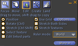
The Edit button lets you position, rotate, stretch your object, or change its texture.
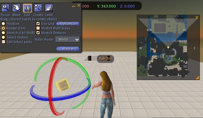
Let's click on Position. Then, your object will have a red, green, blue arrows on it. The red line is the x-axis, representing West/East line, with the arrow pointing to the positive side (East). The green line is the y-axis, representing South/North line, and blue is the z-axis representing up/down. You can then drag these arrows to position your object.
Try the various radio check-boxes for Position, Rotate, Stretch.
Snap to Grid
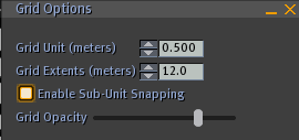
In the Edit mode, there is a “Use Grid” checkbox. When checked, it automatically snaps to the nearest ruler division when you are positioning it. It also works for rotation.
About The Coordinates (about Ruler Mode)
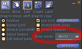
Ruler mode: World = absolute coordinate
Notice there's a “Ruler Mode” menu in the Edit pane. You have these choices: World, Local, Reference. These choices give you 3 systems of coordinates orientation. By default, it is World, meaning that the coordinate axes is oriented the same way as the world's grid. The x-axis is the west/east, the y-axis is the south/north, and the z-axis is the down/up, ALWAYS. When the ruler mode is World, you can consider it as the absolute coordinate system.
To understand the World coordinate: create a cube and select it. Now, turn your avatar to face the same direction the y-axis arrow is pointing to. Now, turn on your mini-map. You will see that you are facing north directly. (When the Ruler mode is World, you can rely on the arrows as the absolutely correct compass)
Ruler mode: Local = coordinate intrinsic to the object
Now, suppose you just made a cylinder. Now, tilt it a little bit (using the Rotate radio box). Now, you want to move this cylinder parallel to its circular wall (the cylinder's directrix). In this situation, you want a coordinate system oriented such that the z-axis is coincident with the cylinder's directrix. Because, this way you will only have to change the position of the cylinder in only one coordinate — the z-axis. This is the option “Ruler mode: Local” is good for. Basically, each object has a intrinsic coordinate orientation, and you can position a object relative to this intrinsic coordinate. When you rotate/tilt a object, the intrinsic coordinate rotate/tilt with it. So, for example, if you create a cylinder, and tilted it a bit, and the intrinsic z-axis will tilt with it. So, when you want to move a cylinder “up” in the direction of its top cap, you can set the “Ruler mode” to “local” and do this easily.
Ruler mode: Reference = user defined coordinate orientation
Suppose you are building a house facing 30°. You need to put build and position furniture inside the house. It would be nice, if the xyz-axes are parallel to your house's walls. This would make positioning things much easier. This is when you need a user-defined coordinate orientation, and is what the “Ruler mode: Reference” is for.
To test this reference ruler mode, try this:
Create a cylinder. Tilt it a little bit. Now, select the menu [Tools ▸ Use Selection for Grid] or press shift-g. This will set your current selected object's intrinsic coordinate orientation as the reference orientation. Now, create a cube. Now, set the ruler mode to Reference. You will now see that the position/rotation etc are using the cylinder's intrinsic grid.
Moving Objects Freely
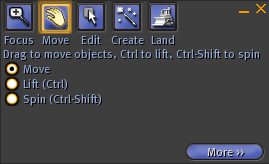
The move button allows you to move objects in a free way.
You have the position tool that moves the object in the direction of the coordinate axes. But sometimes you just want to grab a object and move it freely. This is done with the Move button.
Technically, what happens in a free-move mode is that, the object is constrained to move on the xy-plane. Forward/backward/left/right movements of the mouse will bring the object farer/nearer/left/right with respect to the view point (the camera).